Note
Pay attention to the selected function and what wiring diagram you are navigating to when following a signal. It is possible to navigate to wiring diagrams that are not directly related to the selected function.
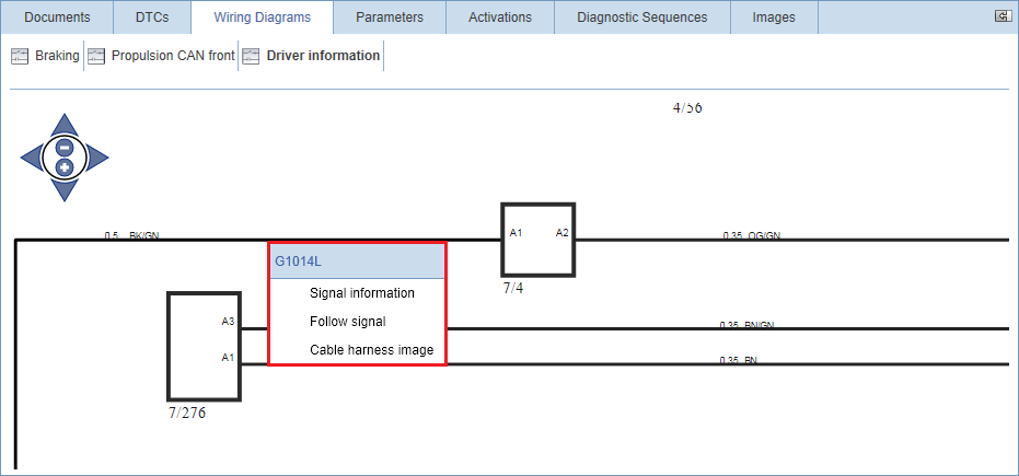
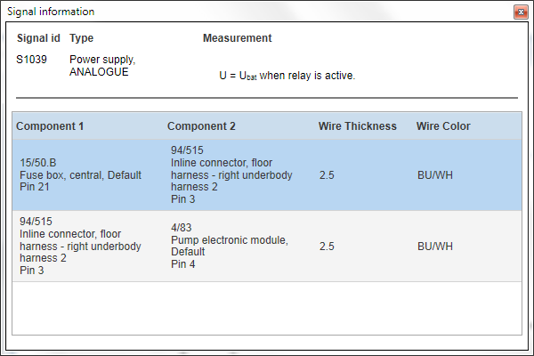
Signal information for a wire is accessed by right-clicking the signal and selecting . This opens a pop-up containing a table with complete information about the signal.
Above the table you can see the signal ID of the selected wire, the type of signal, the expected measurement value. The table indicates what components the wire is connected to including the wire thickness and colour.
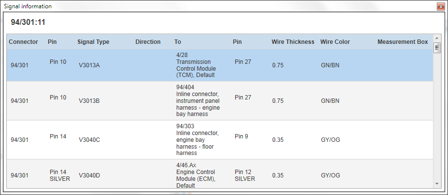
Signal information for inline connectors is accessed by right-clicking an inline connector and selecting . This opens a pop-up containing complete information about connections to the inline on all pins. The pin selected when opening the signal information is shown at the top of the table.
The table shows signal type, direction, closest connected component or connector, pin on connected component or connector, wire thickness and colour. If applicable you can also see the measurement box pins to be used when measuring the signal.
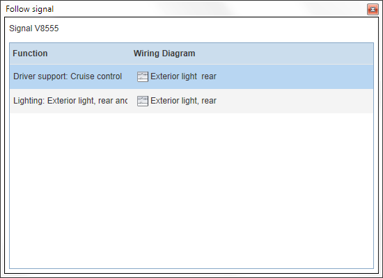
To follow a signal to another wiring diagram, right-click a signal and select . This opens a pop-up containing a list of functions in which the signal is used. You can also see in what wiring diagrams the component is shown.
When you have followed a signal to another wiring diagram, the selected signal is accentuated with a thicker line.
Note
Note
Pay attention to the selected function and what wiring diagram you are navigating to when following a signal. It is possible to navigate to wiring diagrams that are not directly related to the selected function.
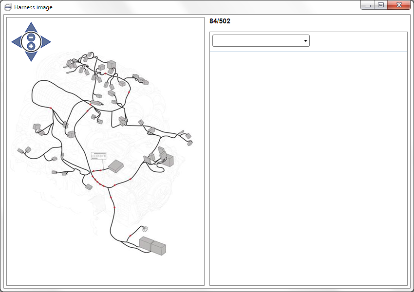
Cable harness images are accessed by right-click a signal and selecting . Cable harness images show the location of connectors, ground points, branching points and location of the harness label. When opening a cable harness image, the corresponding endpoints of both sides of the wire are highlighted in the image. By clicking a connector in the image, pinout for the connector is shown in the right-hand panel.
Note
Note
Harness images are not automatically filtered to show connectors, splices and branches that are valid for a specific vehicle. They should be considered as a “master harness" that shows all possible connectors and branches for all vehicle variants.