Note
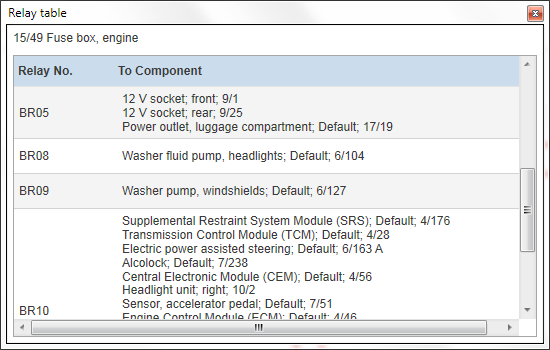
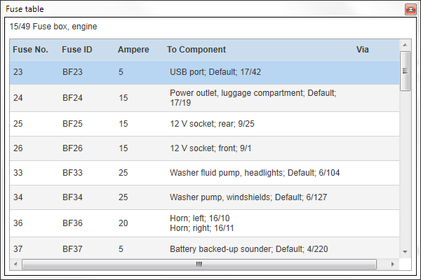
The Relay table option is only available for relay components and the Fuse table option is only available for fuse box components.
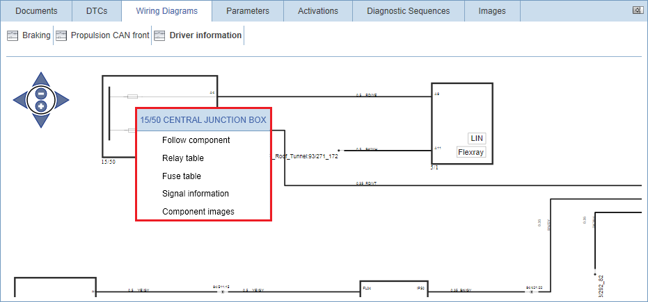
By right-clicking a component in a wiring diagram, a drop-down menu containing options for the selected component is shown.
Read more about each option in the subsections below.
Note
Note
The Relay table option is only available for relay components and the Fuse table option is only available for fuse box components.
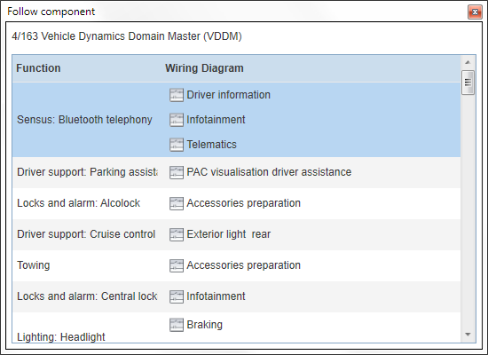
Follow a component to another wiring diagram by right-clicking the component and select . This opens a pop-up containing a list of functions in which the component is used. You can also see in what wiring diagrams the component is shown.
When you have followed a component to another wiring diagram, the component is highlighted in blue.
Note
Note
Pay attention to the selected function and what wiring diagram you are navigating to when following a component. It is possible to navigate to wiring diagrams that are not directly related to the selected function.
A fuse table is accessed by right-clicking a fuse box component and selecting . This opens a pop-up containing a list of all fuses valid for the current vehicle.
The list contains the fuse number, fuse ID, amperage of the fuse and what component the fuse provides power feed for. If applicable, you can also see any components the power feed goes via before reaching the component the fuse provides power feed for.
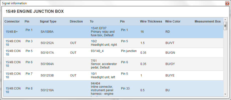
Signal information for a component is accessed by right-clicking the component and selecting . This opens a pop-up containing a table with complete information about all connections to the component. The pins shown on the wiring diagram where the signal information was accessed from are highlighted in blue. Pins not shown in the wiring diagram are not highlighted.
The table shows connector, pin, signal ID, direction of the signal, nearest connection, pin of nearest connection, wire thickness and colour. If applicable you can also see the measurement box pin to be used when measuring the signal. By hovering the mouse over a row, the expected measurement value is shown.
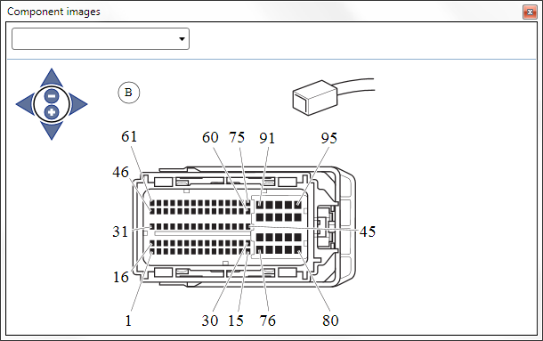
Images for a component is accessed by right-clicking the component and selecting . This opens a pop-up containing a drop-down menu of relevant images.
The following image types can be selected from the drop-down menu in the upper left-hand part of the window:
Component images
Location images
Pin-out images
Layout images (only available for relays and fuse boxes)
Zoom images in and out by using the + and - buttons in the zoom slider, placed in the upper left corner of the images. It is also possible to zoom images by using the scroll wheel on your mouse. Pan images by using the arrows in the zoom slider or grab and drag to desired position by using the mouse.