When selecting a component in the Ranked list, the relevant wiring diagrams are displayed under the tab. Once a component is selected, it is highlighted in the wiring diagram which makes it easy to track. For some components there is more than one wiring diagram available. In such case all available wiring diagrams are listed above the currently viewed wiring diagram.
The wiring diagram content is automatically filtered based on the VIN of the current vehicle. Please note that a wiring diagram may look different depending on the configuration of the vehicle.
Navigation and general functions
The zoom slider is placed in the upper left corner of the wiring diagrams and is used for navigation. Zoom in and out by using the + and - buttons in the zoom slider. It is also possible to zoom by using the scroll wheel on your mouse. Pan by using the arrows in the zoom slider or grab and drag the wiring diagram to desired position by using the mouse.

Other general functions used when working with wiring diagrams are explained in the table below.
|
Functionality |
Description |
|
|---|---|---|
|
Mouseover |
Holding the mouse over a signal increases the line width to show its path in the wiring diagram. Holding the mouse over a component increases the line width of the component and a tooltip containing the name of the component is displayed. |
|
|
Access information |
View more options and information by right-clicking components and signals in the wiring diagram. See the subsection below for further information. |
|
|
View in expanded mode |
Click the |
|
 icon next in the upper right part of the panel to collapse the left-hand menu panels and view the wiring diagram in expanded
mode. Click the
icon next in the upper right part of the panel to collapse the left-hand menu panels and view the wiring diagram in expanded
mode. Click the  icon to return to default mode.
Component and signal functions
Additional information and functions are accessed by right-clicking different objects such as components, wires and inline connectors in the wiring diagram. See the following two articles for additional information:
Symbol legend
In the tables below, commonly used symbols in wiring diagrams are presented.
Components
|
Symbol |
Description |
Explanation |
|---|---|---|
 |
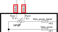
Pin information |
Connector name and pin number is shown inside the component symbol next to the connected wire. |
 |
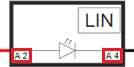
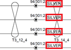
Special connector terminal material indications |
Special connector terminal materials are shown near the associated pin. Typically these are gold or silver but if nothing is indicated, the terminal material is always tin. |
Internal component symbols
|
Symbol |
Description |
Explanation |
|---|---|---|
 |
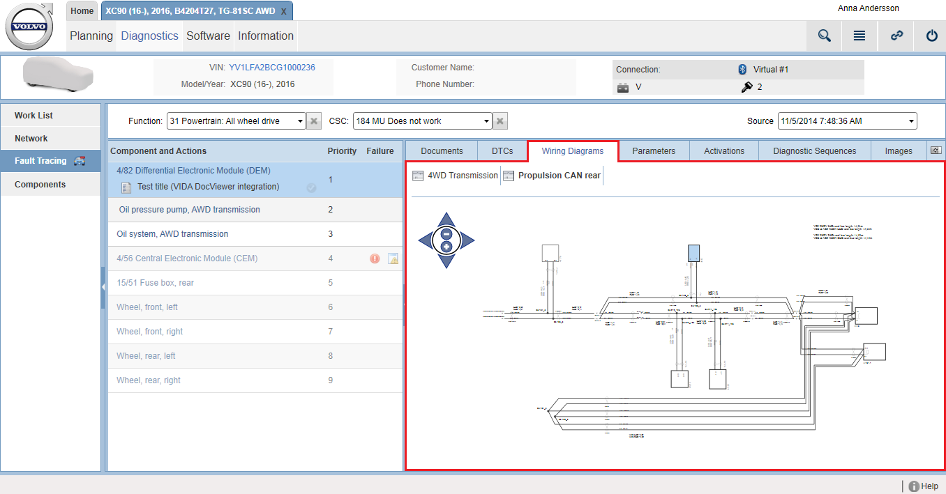
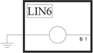
Network membership |
Components that are connected to data communication networks contain symbols for the networks which the component is connected to, such as CAN, Flexray and LIN. Please note that network membership symbols are typically not shown in wiring diagrams that only contain information for a specific communication network. |
 |
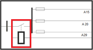
Fuse |
Fuses are indicated as internal symbols in components. |
 |
Relay |
Relays are indicated as internal symbols in components. |
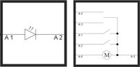 |
Other internal symbols and circuitries |
Some components also illustrate internal component circuitry and components such as switches, motors and lamps. |
Wires
|
Symbol |
Description |
Explanation |
|
|---|---|---|---|
 |
Wire colours |
The colour of a wire is indicated by the abbreviation shown on the wire. All abbreviations are presented below. |
|
|
BK |
Black |
||
|
BU |
Blur |
||
|
BN |
Brown |
||
|
GN |
Green |
||
|
GY |
Grey |
||
|
OG |
Orange |
||
|
PK |
Pink |
||
|
RD |
Red |
||
|
VT |
Violet |
||
|
WH |
White |
||
|
YE |
Yellow |
||
|
SCRN or SCREEN |
Shielded |
||
 |
Wire cross section area |
The cross section area is indicated on each wire next to the wire colour. The cross section area is indicated in millimetres. |
|
 |
Signal type |
The line colour of a wire indicates the signal type of the wire. As an example, constant 12 V-feed is indicated with red line colours. |
|
 |
Broken wire |
A dashed wire is indicating a wire that is most likely causing a problem. |
|
 |
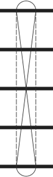
Twist |
Twisted wires are indicated by an “8”-symbol stretching over the wires that are twisted together. |
|
 |
Multicore |
Multicores are cables with multiple conductors, commonly used with coaxial cables or when a wire is shielded. The shield is shown as a wire with the colour shown as SCRN or SCREEN. The symbol indicates that a multicore stretches over the shield as well as the other wires which are shielded. |
|
 |
Twisted multicore |
Twisted multicores are cables with multiple conductors that are twisted together, which are also shielded. The shield is shown as a wire with the colour shown as SCRN or SCREEN. The symbol is a combination of the multicore symbol and the twist symbol. |
|
 |
Branching point |
Branching points (also known as splices) are shown with the following symbol and associated branching point ID, which typically
starts with |
|
 |
Reference |
References are used when a wire continues on another wiring diagram. |
|
Ground points
|
Symbol |
Description |
Explanation |
|---|---|---|
 |
Single connection ground point |
Single connection ground points are indicated with a single ground symbol together with a ground ID such as |
 |
Multi-connection ground |
Multi-connection grounds are indicated with a ground symbol with multiple connections together with a ground ID. |
 |
Case ground |
Case grounds are indicated as connected to a component, but without a ground ID. |
Inline connectors
|
Symbol |
Description |
Explanation |
|---|---|---|
 |
Inline connector |
Inline connectors are indicated together with the inline ID and the pin number of the connector. |
 |
Inline connector special terminal material indications |
Special inline connector terminal materials are shown near the associated pin. Typically these are gold or silver but if nothing is indicated, the terminal material is always tin. |