Note
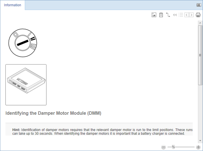
Within several documents, an image of a VCT2000 is displayed (see example in image above). Clicking such an image triggers a script and a pop-up opens telling you what to do.
The functionalities available under the tab are used for various vehicle repair procedures. Some examples are various calibrations, programming of control modules, readout of stored tyre pressure sensor values etc.
Each area of the page is explained in the subsections below.
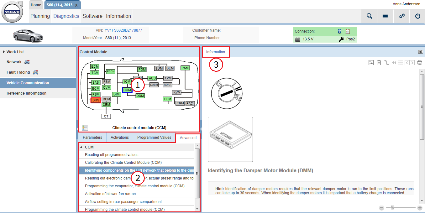
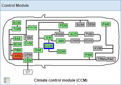
In the Control Module panel, deviations on the vehicle's network communication are presented in a graphic. The graphic reflects the vehicle's network with all control modules' status at the latest readout.
The colour of the control modules in the graphic varies depending on status:
|
Colour |
Description |
|---|---|
|
Green |
Control module responsive to communication. |
|
Orange |
Control module not responsive to communication. |
|
Grey |
Control module not part of the vehicle configuration (it may, however, be in the relevant vehicle model). |
An explanation of the colours is accessed by clicking the  icon.
icon.
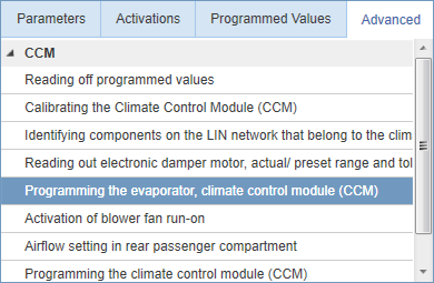
By selecting a control module in the graphic, the list under the tab is populated with documents related to the selected control module.
In this list, documents for e.g. programmable customer parameters, adaptations and calibrations related to the selected control module are listed.
The list is in some cases structured in categories. By clicking a document in the list, it is opened under the tab on the right-hand side of the screen.